First of all, let’s clarify: 3D compass models are axonometric. They clearly display the detail. These are not just three projections of it, this is a visual three-dimensional image.
Types of axonometric projections:
Rectangular;
Oblique.
In turn, the axonometric rectangular projection is:
Rectangular isometric (most common);
This tutorial covers all the steps to draw a nice vector compass with a magnifying glass. I hope you enjoy learning this lesson. First let's open new document. As shown in the image above, we will name the file and then enter the size of the artboard.
Make another circle inside the first circle. After creating the circles, select two circles and make them. Image shown below. After creating the connection, the circle is cut from the middle. Let's move on to the next step and fill this shape with a radial color gradient. The gradient value is given below.
Rectangular diametric.
The compass allows you to build both types of projections.
The construction scheme in the Isometric Compass is as follows:
1. The drawing plane is selected in the given coordinate system.
2.The basis of the part is created - a sketch.
3. A three-dimensional workpiece of a part is created (using rotation, extrusion, kinematics or section).
After filling the gradient, our image will look something like the image above. Let's go ahead and make the shape as shown below and marked with a red arrow. Fill this image with the gradient color. The gradient value is shown in the image below.
Let's make the shape shown in the image below and fill this image with the same gradient color that was used above. Rotate the gradient 180 degrees. This way the gradient will be cancelled. Place the gradient filled lines on this shape marked with a red arrow. You can fill the lines with a gradient of your choice.
4. Using this blank, the necessary elements with pre-created sketches are cut out or additionally glued to it.
Three-dimensional modeling in Compass, sequence of actions:
- Before drawing, select the xzy isometry (in the editor window, View menu, Orientation tab).
- Add the Origin of coordinates in the model tree and make a choice on which plane your drawing will be located (most often on the horizontal, zx).
- Sketch construction is identical to the two-dimensional editor, the same toolbars.
- After completing the sketch, before starting to build the model, do not forget to press the “sketch” tab, otherwise you simply will not see the necessary buttons.
- Select commands from the editing panel: extrusion, rotation, sectional, kinematic. You need one to build a 3D model.
All is ready!
After placing the form, our image will look like this. Let's move to the bottom of the compass. Make a circle shape as shown in the picture below. Fill this shape with the gradient color with the values shown in the image below. Then we will make another circle inside this circle. Fill it with the gradient shown in the image above, but change the orientation of the graduation. As you can see the gradient line right now. Now with the Gradient Tool selected, we'll drag this line again to change the orientation of the gradient.
Creating drawings in Compass
This section includes drawings of parts and assemblies made in Compass. All of them can be downloaded and used as a sample for your own projects, documentation, coursework or dissertation.
The Compass 3d program is one of the best in the field of solid 3d modeling. The Russian interface makes work easier and is suitable for both construction design and the engineering industry.
To move to the next step, make another circle inside the circle shape and fill it with a random color gradient. To do this, you can choose any gradient color. Now we have made one part of the compass silver. Let's move on to the next step and make 2 more circles inside this shape. Fill the circles with colors as shown below.
We will place a circle of black color in the smallest circle. Now the basic structure of our compass is complete. So we're ready to start creating the inside of this compass. You would see how the numbers fit into the clock, so we will apply the same method to this part of the compass.
With the help of Compass, you can prepare production, develop documentation, technical and design - everything necessary for the release of a product. In addition, it is possible to transfer the geometry of the product to the calculation package and transfer it to the development package of the control program for the CNC machine.
Main functions:
- Extensive 3D modeling capabilities using a variety of tools.
- Modeling, including from sheet material - sheet body, bends, holes, beads, development of a sheet body.
- Facilitation of the design of casting molds - connectors, slopes, cavities with a given shrinkage.
- Preparation of all necessary documentation, technological and design, from drawings and specifications to tables, diagrams and text documents.
- Libraries containing many commonly used standard elements.
- Possibility of integration with many other CAD\CAM\CAE systems.
Libraries Compass 3D

Download the program for drawing a compass at maximum speed
Now we will make a small move on the top side. We will do another round in a similar manner and use the same method as above. Let's go ahead and insert the third and last row, we also used the same technique for this. Once we finish placing the rows, we will place the corresponding numbers.
The next step is to make the needles. To make the needles, let's create a shape as shown in the image below. We will fill this shape with a gradient with the value shown in the image below. Remember that the center part of the gradient has 2 nodes; one node is hidden behind another node, but we have to give a gradient value for both nodes.
Due to the application libraries built into the program, the work of the designer in Compass 3d is practically automated. That is, you can perform many routine actions easily and quickly using built-in tools - insert a three-dimensional assembly from standard products into a drawing, make standard calculations and much more.
Now that we have done one side of the needle, we will continue with the other side of the needle. We'll only change the color from red to green and it will look like this. Let's attach both of these needles and place them in the center of the compass. We will also change the rotation of the needles. By placing the needles in the middle of the compass, we will make two more circles in the middle of the compass and fill them with a simple gradient. Illustrator will accept the default value, so we don't need to give any value.
Let's go ahead and make some needles as shown in the picture below. Place the shape in the middle of the compass and change the color from black to white. After this, our image will look like this. Now we will place text on the tip of each white needle, indicating the direction.
There are many libraries in Compass; they facilitate design activities. Moreover, the contents of the libraries comply with all Russian GOSTs and are very easy to use, which is often lacking in foreign modeling programs.
The extension of the files contained in the libraries: *.rtw and .dll (Windows Dynamic Link Libraries).
Now we will give the compass a glow. To do this, make a shape using the pen tool as shown in the image below. This will copy the black shape onto the shape made with the pen tool. Select the option marked in red in the image below.
By selecting the specified option, we will see a new shape in which we will fill the gradient color. The window shown below. Remember that we must set the black opacity value in the gradient to zero. The compass adjustment sleeve is copied and pasted into the bottom.
Pinion - Library of Gear Cutters
Now that we have made the compass, let's start working with the magnifying glass. Let's make a circle and fill it with a gradient color. We must use the same technique to create the circle as we used to create the compass. To make a magnifying glass handle, make a box and fill it with the default gradient.
Examples of the most popular libraries Compass:
- Design library – contains screws, bolts, springs, bearings, nuts – many necessary details for insertion into drawings.
- Standard products – a library of three-dimensional models of standard products for insertion into an assembly.
- Compass-Shaft 2D, 3D: this is a calculation system (with a set of Gears programs) of rotating bodies and mechanical gears, both 2d and 3d.
- Compass-Spring: calculation and design of springs.
- APM FEM – strength analysis.
Others include libraries for aerospace, architecture and civil engineering, welding, mechanical engineering, manufacturing engineering, piping, and electrical and electronics.
We will also create another box that will be slightly larger than the first one. Fill it with a gradient color. Once you have made the handle, make two more small rectangular shapes as shown below. Fill the shapes with white and set the Opacity to 20%, then place them on top of the handle.
After placing the mold, the basic structure of the glass is completed. Make another circle inside the magnifying glass as shown in the image below. Now we will place the compass under the magnifying glass shape as shown in the image below. By making a clip mask, the compass will be masked with a circle.
Different versions of the program contain different libraries. The LT version has the least number of them, however, even it has a Design Library. Sets of the libraries you need can be purchased on the corresponding websites.
For connections of one or another library, depending on the program version. You need to either open Service-Library Manager or Service-Connect Library in the main menu. After this, the required library is added to the Libraries section in the main menu.
Creating drawings in Compass
We will now place the magnifying glass above the compass, but remember that the placement must be precise. Rotate the glass to your liking. Remember that you need to rotate the glass, but not the compass clipping mask. We go into the compass clipping mask and increase the size of the compass by 30%.
Now move the magnifying glass with its clipping mask slightly to the top right side of the compass. The final image is complete and looks like this. To download the source file for this tutorial, you must be logged in as a member. to access all exclusive content!
Libraries operating modes: dialogs, menus and windows. It is most convenient to work in window mode. To change the mode, you need to select Tools - Change operating mode.
You can create libraries yourself, from simple ones containing small fragments such as grooves and grooves, to complex custom libraries that will be useful not only for you, but also for other designers. However, to create them you need to have programming skills in languages such as Visual Basic and Borland Delphi.
After all, small and practical items can be just as innovative. If this reminds you of those compass drawings you used in high school, then you're on the right track, but there's so much more to it. For what Ken Nakagaki has done, he takes this principle and makes it a feature-rich automatic drawing tool that can be programmed to replicate a variety of detailed shapes and sizes.
Thus, the pencil lead at the end of the arm moves in a programmed manner on its own. As you can see in the video below, this can lead to some pretty weird shapes. The key to this versatility is automatically adjusting the pen's radius.
Details Compass 3D

In the Compass program, a part model is a separate document type. The modeling order is the sequential execution of a sum of actions (addition, subtraction) with volumetric primitives (prisms, cones, spheres, pyramids, cylinders, etc.).
The shapes it measures are simply converted into digital files that can be drawn, just like those that are pre-programmed. And obviously, what can be done with a pencil can be done with a small knife. Although Nakagaki, in turn, regularly drew the compass, he adapted it to modern times.
But these systems lack the intuitiveness of drawing on paper. We needed a drawing tool that included the benefits of both digital and manual. Throughout the process, Nakagaki relied on 3D printing to give shape to his thoughts.
Volumetric objects in the Compass are formed by moving a flat figure in space. As a result of the movement, a trace remains in the shape of the object. Thus, when rotated around an axis, a circle creates a sphere, a polygon creates a prism.
Most convenient way modeling of a product, which may differ only in nuances - this is the use, as the main model, of a previously completed part blank. When inserting a part into a model, you can save a link to the file in which it was located. This allows all model changes in the source file to be transferred to those products that contain this workpiece. The use of blanks in modeling in some cases increases the speed of design of high complexity.
Various practical applications in manufacturing, education and architecture. This parametric technology provides exceptional benefits quick creation a series of products based on a single prototype. Our core combines the benefits of parametric design, design-driven development, and direct modeling.
This body type is flexibly modeled and is therefore ideal for complex geometries. A comprehensive set of features helps you create accurate plans, clear diagrams, documented reports, and even prepare vector illustrations. Below is full list supported file formats.
The model can contain not only blank parts, but also their mirror copies. In this case, models of parts with mirror symmetry are created in seconds. At the same time, the part tracks the changes that are made to its prototype and can independently rebuild in accordance with these changes, maintaining symmetry.
It is also possible to create sections and cuts in the part. For example, in order to stamp a bumper (one of the parts of road barriers) you need a punch and a die. They are made using a milling machine. Control of the shapes of the manufactured punch and matrix should be carried out using a set of templates that correspond to the sections of the bumper every 50 mm. Constructing such sections using descriptive geometry methods is very labor-intensive work. To make it easier, there are special functions of Compass 3d.
This article will surely attract the attention of all adventure lovers. From now on, you can count on four main points at your fingertips. Coming in a variety of shapes and colors, each of these apps will keep you from straying or losing track of your adventures. Compass in high resolution, ready not to disappoint us and to guide us accurately at any time. His classic style reminds us of the first devices of this type with the arrangement of corners around a circle and the ability to change the background image.
Every trip requires a companion that gives us the ability to insert latitude and longitude parameters and even set navigation routes. Interactivity options include detailed maps, calculating distances between two points, and storing our latest intersections.
Create a 3d model of the fender, set the position of the section planes and use the “part drawing” command. All sections and types of parts that you need will appear automatically in the Compass-Graph drawing. A 1 to 1 scale drawing sheet can be used as a basis for templates.
Flat figures that serve as the basis for the formation of bodies are called sketches, and the movement of sketches that forms a form is called an operation.
With over fifteen different visual themes to choose from, this application has an impressive graphical level and allows you to change appearance needles depending on our mood. To go for a refreshing pint, you only need to activate this app and follow the compass to the nearest bar to your position. The developers of this application also wanted to equip it contact information about the bar, customer reviews and a list of all other options in the area for beer.
The phrase “look at Cuenca” has accumulated many and varied meanings throughout history. Millions of car parks are available with an application that many consider essential if you need to find a place to store our car without much difficulty. Fully free compass shows us the exact orientation and number of steps in meters to the nearest parking lot. You can also read customer reviews or open a map to share your location on social media.
Sketches Compass 3D
![]()
Compass-Graph is a drawing and graphic editor that allows you to draw sketches on a plane. It provides everything for editing and building images, parameterization tools and service capabilities. An exception is that a number of design objects and technological designations cannot be entered into Compass-Graph.
Additionally, the wallpaper can be interchanged with multiple options and darkened depending on your taste. Among other functions, we can also find latitude and longitude information, or adjust the accuracy of the data. We will also work with visualization and rendering of 3D objects.
New current mark: 1 New current thickness: 2. Entities generated from now on will have these values for their boost and extrusion. Through the coordinate. The object will be shown from the selected point towards the origin. Manipulation of three axes and compass.
The sketch may contain images from drawings or fragments previously prepared in Compass-Graph. Thus, drawing and design documentation helps when creating a 3D model. Sketch locations:
Orthogonal coordinate plane;
Auxiliary plane, with a given position;
Already constructed body (its flat face).
The following operations can be performed with a sketch:
- Kinematic – the sketch moves along a specified guide.
- Rotation around an axis located in the sketch plane.
- Extrude perpendicular to the sketch plane.
- The body is constructed using several sketches-sections.
Each action has additional options that allow you to change the rules for constructing bodies:
- The sketch can be rotated at a given angle and the direction of its rotation relative to the plane of the sketch itself, and you can also select the type of body.
- You can extrude a sketch with a given direction and distance relative to its plane, and you can also enter a draft angle when necessary.
- The kinematic operation is carried out with a given orientation of the generatrix relative to the guide.
- The construction of a body by section is done with an indication of whether or not it is necessary to close an already constructed body.
Any type of operation allows you to create a thin-walled shell and set the direction and thickness of the wall, both inward/outward and on both sides of the body formed by the operation.
After the base body is created, gluing (cutting) of additional volume takes place. Each such volume is an additional matter that was formed after all the above operations with new sketches.
When choosing the type of operation, you immediately indicate whether the body being created is subtracted from the main volumes or added to them. If we are talking about gluing (cutting) operations, then more options will be available than in the basic operation. These additional options simplify setting parameters. For example, when creating a through hole, you can not specify the calculation of its length, but use the “through the entire part” option and, when creating a boss, indicate that it should be built to the desired surface.
Pinion - Library of Gear Cutters

This library is intended for those who design medium module (1-12 mm) involute gear cutting blocks. It also allows you to automatically create graphic documents in the Compass system.
The library helps in solving the following problems:
Calculates the geometric parameters of the cutter;
Generates the values of accuracy indicators and technical requirements in accordance with the accuracy of the wheel being cut;
Builds a working drawing of a cutter (or image) with a given view;
Builds a 3D model of a logger.
Conveniently, the resulting graphic documents can be automatically edited in conventional Compass editors.
Pinion works in Compass versions 11 and higher and does not have any requirements for operating system and your PC hardware, in addition to standard ones.
Installation and launch
In order to install the library, you should run the setup.exe file and follow the instructions of the installation wizard. By default it will be installed in ...\ASCON\SAPR-project\Pinion.
In order to connect the installed library, you need to do the following:
- Go to Tools->Library Manager, the Library Manager window will appear.
- Call the “add description – application library” command in it.
- In the pop-up dialog box, specify the file pinion.rtw (the path is indicated above, or you indicated it yourself, look there), click “open”.
- The library properties dialog box will open, click OK. The library you need will now be listed in the Library Manager.
- Select "Library of gear cutters" and in context menu select "connect". You can work with the library.
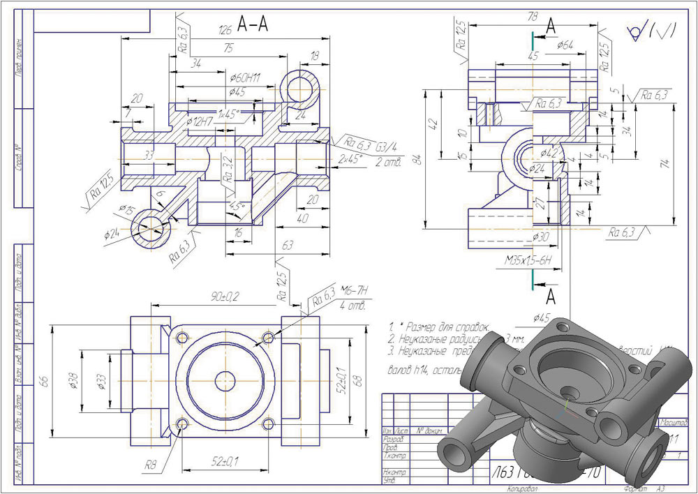
The first lesson in two-dimensional modeling will be devoted to the topic of how to make a drawing in a compass. It is the creation and design of a drawing with a specification that is considered the completion of any modeling.
To use a drawing effectively, it is necessary to format it as correctly as possible. To make a drawing model in a 3D compass, you must adhere to the basic rules of drawing. The program already has the ability to create standard and projection views, callouts, sections, view breaks, etc. The user just has to use all the necessary tools and operations.
Let's move on directly to how to make a drawing of a part in a compass. Each drawing, 3D model, specification and fragment - separate file, so creation begins by creating a new file.
By default, the settings are A4 sheet format. Now you can create a drawing, as desired, and orientation.
The next step is to look at how to make a drawing into a 3D compass from a 3D model. Constructing a drawing from a model allows you to significantly save time and avoid errors during construction additional types and sections, since views and sections are generated automatically.
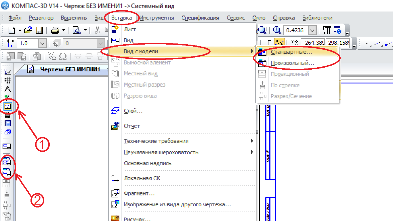
There are two ways to insert a view from a model; both methods are equally convenient and simple. In compass 3d, you can make a drawing from a 3D model by selecting an insert in the top menu, then select “View from the model”, and select standard views (front, left, top), or arbitrary, select parts, etc. You can assign any type to arbitrary; this is done at the bottom of the insertion panel.

Today we only looked in general terms at how to create drawings. Each user masters most of the nuances independently. Ask all possible questions in the comments.